Offshore FandampG System CFD Analysis
02 March 2015
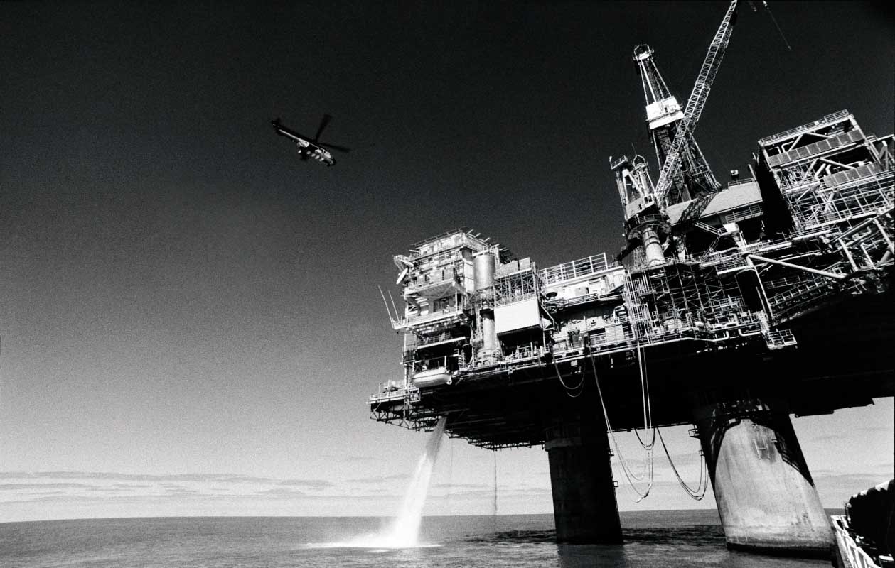
This case study involved a survey of an existing offshore F&G system, which was suffering from equipment obsolescence and failures, leading to parts of the system being bypassed, and leaving some process areaa with reduced detector coverage.
Our remit was to survey the existing gas detector layout, confirm or otherwise, that coverage was adequate and also assess the random hardware failure rate of detection loops, which initiated mitigation systems, such as the platform water deluge systems.
It is interesting to note at that this point, that the HSE surveyed hydrocarbon detection rates over an 8 year period during the late 1990's, finding only 60% of leaks were automatically detected, while the balance were detected by people through smell or sound. It is also interesting to note, that traditionally, point gas detectors have been located on a 5m 3D grid pattern. This grid pattern dimension being loosely based on the structural damage, which could occur with the ignition of 5m sphere/cube of gas.
What also has came out of the research, is that a good mix of technologies should be used for gas detection systems, such as point, beam and acoustic.
It is also interesting to understand what affect a deluge system has on a gas cloud, when ignited. Dynamic simulations can demonstrate how cooling and displacement of oxygen by a deluge system, can limit the intensity of an explosion, when a deluge operates successfully.
For this case study, Computational Fluid Dynamics (CFD) modeling was used to determine the possible module fill volume that could occur, during an undetected leak.
Prior to the CFD, critical module fill volumes were determined during explosion analysis, where overpressure experienced at structural boundaries following delayed ignition was examined. The explosion analysis typically identified critical fill levels of 25% for the Well-Bay, 5% for the Upper Process Module etc.
Our work began by first carrying out an 'As Built' survey of the platform gas detection system, to ensure the dimensional locations of the detectors were correct, with respect to the platform structure, which was necessary for the CFD analysis.
Once the platform module dimensions and detector locations had been established, the CFD was run for various leak sizes, leak directions and wind speed and direction. (Wind data was obtained from the platform Wind Rose). The CFD modeling then produced results, which were plotted showing Percentage Module Fill for each leak scenario.
It was then possible to identify which scenario effectively beat the gas detection system, allowing the gas cloud to build to a critical level. Additional detectors were then added to the model, until critical volumes were not exceeded.
The results from the CFD analysis identified two modules, which infringed the critical fill volume. The infringement was rectified, by the addition of some 10 extra detectors in the two modules, which brought down the gas cloud size to below the critical fill volume.
The random hardware failures calculation established that the hardware alone achieved a PFD of SIL 1, however, this did not take into account the probability of detecting a gas leak. To get a more realistic indication of probability of catching a leak and the deluge operating, a factor of detection rate should be included.
As with all reliability calculations, we are looking at orders of magnitude in risk reduction via qualitative and quantitative techniques. By carrying out such CFD modeling exercises, an organization can start to put figures on probabilities of detection rates and mitigation reliability, demonstrating provenance of their systems to any external organizations.
More Case Studies
Chemical Facility - Hardwired Safety Instrumented System (SIS) UpgradeAircraft Collision during Taxi for Take off

What We Do
We offer a full range of functional safety services, including Functional Safety Regulations, Functional Safety Audits and Assessments, HAZOP, Risk Reduction Targets, Design, Verification and Validation, Commissioning and Operation, and more.
Services we offer